


PiWave 150 MS/s Bipolar DAC
PiWave 150 MS/s Bipolar DAC
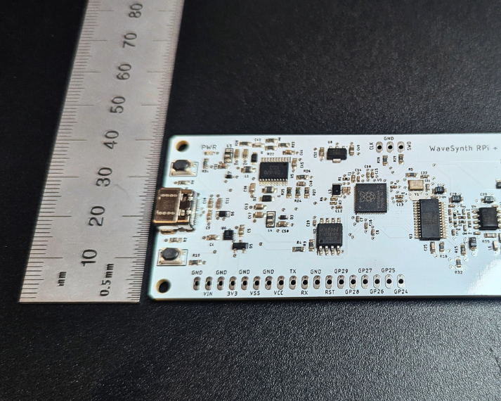
The PiWave DAC is an open-source, high-speed digital-to-analog converter (DAC) reference design created for engineers who need fast, precise waveform generation without the complexity of an FPGA.
Capable of sample rates up to 150 MS/s, PiWave DAC uses a Raspberry Pi RP2350 microcontroller and its programmable I/O (PIO) subsystem to directly control the DAC's parallel input at high speeds. This architecture eliminates the need for an FPGA allowing the user to create complex waveforms in a open source C programming environment.
PiWave DAC is powered and programmed through a single USB-C connector, making it easy to integrate, evaluate, and deploy. Output signal conditioning features include a third order analog filter and a selectable output impedance of 1M or 50 Ohm. The design is available in 10-bit, 12-bit, and 14-bit variants, giving users flexibility to balance speed, resolution, and cost.
Product features
Product features
PiWave is the first ever microcontroller based 150 MS/s parallel controlled DAC that does not require a FPGA or highly specialized microprocessor. It uses the Raspberry Pi RP2350 microcontroller's innovative Programmable Input/Output (PIO) state machine to send parallel data to the DAC at a maximum clock rate of 150 MS/s. You can find example code that shows how to configure the PIO state machine to control the DAC by accessing the "Getting Started with Anabit's Precision Logger" link below. All example code was developed in the free Visual Studio Code programming environment using the C programming language.
The PiWave employs a fixed 3 pole reconstruction filter at the output of the DAC with a cutoff frequency of ~27 MHz. This simple filter approach was chosen for two reasons:
--> Keep the high speed DAC design flexible for multiple use models
--> Keep the cost down
To understand the filter design in more detail as well as its pros and cons refer to the getting started tutorial.
Specifications
Specifications
--> Maximum DAC sample rate: 150 MS/s which is based on the RP2350's maximum clock rate of 150 MHz. The RP2350 can be over clocked, but maximum sample rate of DAC IC is 165 MS/s
--> DAC resolution variants available: 10 / 12 / 14 bit
--> Bipolar output amplitude:
--> 6.3 Vpp with 300 kHz sinewave
--> 5.9 Vpp with 2 MHz sinewave
--> 3 Vpp with 9 MHz sinewave
--> 1 Vpp with 16 MHz sinewave
--> LCL output filter bandwidth: ~27 MHz. Estimated attenuation: 30 MHz = -3.8 dB, 40 MHz = -6.7dB, 50 MHz = -9.2 dB, 75 MHz = -15.1 dB, 100 MHz = -22.2 dB
--> Please note that at higher frequencies max amplitude drops due to filter but also because of amplifier gain roll off
--> Output impedance: 50 Ω or 1 MΩ. Selectable, tied to pin GPIO 22 on the RP2350
--> Power input: USB-C or 2.54 mm pin header, max current 300 mA and max power 1.5 W with 50 ohm output Impedance. At 1 Mohm max current is 200 mA and max power is 1 W.
--> Memory: the RP2350 microcontroller has 520 kB of SRAM and is connected to a 16 MB flash memory IC via QSPI. See the RP2350 datasheet for more information.
Bulk Pricing and Discount Information
Bulk Pricing and Discount Information
Discount for large orders
5% discount for quantities of 10 or above, automatically applied at checkout. Contact Anabit for bulk pricing on quantities of 50 or more.


Resources
-
Tutorials
Explore tutorials and getting started guides to get the most out of your product.
-
Open-Source Downloads
Download open source hardware files, including PCB design files and schematic files
Download -
Forum & Discussion
Have product questions or need technical support? Have general questions or insights to share related to data converters? Join the Anabit forum!
Anabit Forum